Tag Archives: Digital Modes

NBEMS – An Introduction Using Fldigi and Flmsg presentations

I was asked to give a presentation on using Fldigi and Flmsg in NBEMS — Narrow Band Emergency Messaging System (or Software).

Framework

The framework I chose to use for the presentation slides is called reveal.js. It is an HTML framework meaning it will run in any HTML 5 capable browser. Looks a little better than a PowerPoint presentation.

Navigation

Useful navigation keys in the presentation. In addition to navigating with the keys below, you can swipe (tables/smartphones) or use the navigation arrows on screen in the lower right.

Toggle full screen: press [F11].

Advance to the next slide: press [n] or [SPACEBAR].

Go back to the previous slide: press [p] or press and hold the [SHIFT] key while pressing the [SPACEBAR].

Display presentation overview: [ESC] then use the arrow keys or mouse to select a slide. [ESC] again will exit overview mode.

Links

Clickable links are colored in blue text.

Presentations

Three variations are available: presentation version is viewable in a browser. Printable version for printing or saving in a different format (Chrome, Chromium, and variants compatible only). Finally a PDF version.

They may take some time to load because I left original images untouched and some were a couple MB in file size.

Slides

Introduction to NBEMS

The presentation is about 60 minutes in length.

Presentation version
Printable version
PDF version

This presentation was given at the following meetings:
Lorain County ARES on 10/21/2018.

VHF/UHF NBEMS

This is an older version without the HF information.

The presentation is about 60 minutes in length.

Presentation version
Printable version
PDF version

This presentation was given at the following meetings:
Medina County ARES on 11/10/2015.
Mansfield Hamfest on 2/21/2016.

Ohio Section Journal – The Technical Coordinator – October 2018 edition

One of the responsibilities of the Technical Coordinator in the Ohio Section is to submit something for the Section Journal. The Section Journal covers Amateur Radio related things happening in and around the ARRL Ohio Section. It is published by the Section Manager Scott – N8SY and articles are submitted by cabinet members.

Once my article is published in the Journal, I will also make it available on my site with a link to the published edition.

You can receive the Journal and other Ohio Section news by joining the mailing list Scott has setup. You do not need to be a member of the ARRL, Ohio Section, or even a ham to join the mailing list. Please sign up!

If you are an ARRL member and reside in the Ohio Section, update your mailing preferences to receive Ohio Section news in your inbox. Those residing outside the section will need to use the mailing list link above.
Updating your ARRL profile will deliver news from the section where you reside (if the leadership chooses to use this method).
Go to www.arrl.org and logon.
Click Edit your Profile.
You will be taken to the Edit Your Profile page. On the first tab Edit Info, verify your Email address is correct.
Click the Edit Email Subscriptions tab.
Check the News and information from your Division Director and Section Manager box.
Click Save.

Now without further ado…


Read the full edition at: http://arrl-ohio.org/news/2018/OSJ-Oct-18.pdf

THE TECHNICAL COORDINATOR
Jeff Kopcak – TC
k8jtk@arrl.net

DSCF5081 K8JTKHey gang,

Digital mode access points, often called hotspots, have been in the news lately. Those are the 10mW personal devices used by digital operators to cover a relatively small area like a house, car, or hotel room. Instead of tying up a gateway repeater, which largely connects local users to the Internet, many have opted for these low-powered devices to provide similar functionality. Advantages over a repeater are the hotspot owner has complete control over which reflector, repeater, or talkgroup their hotspot is connected to. They are not beholden to the preferences of the repeater owner and have the flexibility to use their hotspot however they’d like. Many use them mobile in the car or take them on a trip allowing them to enjoy their favorite digital modes where there may not be repeater coverage.

Hotspot devices in general are about the size of a deck or two of cards and require an Internet connection, computer to run the software, application or web browser for configuration, and a radio capable of operating each mode. An Internet connection can be your home WiFi or cellphone hotspot (as in WiFi-hotspot). The original OpenSpot was the only device that required a wired Ethernet connection. A PC computer may serve as the Internet connection for USB access points. The computer could be a Raspberry Pi in many cases or might be completely self-contained. A web browser or application is needed to make configuration changes and adjustments such as call sign, transmit frequency, mode, or network. These hotspots are the RF gateway to the internet which means a radio capable of transmitting and receiving that mode is also required. Few hotspots today are single mode like the D-STAR DVAP. Nearly all on the market are capable of operating multi-mode and connecting to associated networks. To operate DMR the user would need a capable DMR radio, a capable Fusion radio for the Fusion networks, and so-on.

Hotspots can utilize the many available modes & networks:

  • DMR: BrandMeister, DMRplus, XLX
  • D-STAR: DCS, DPlus, XRF, XLX
  • Fusion: FCS, YSFReflector
  • NXDN: NXDNReflector
  • P25: P25Reflector

A keen eye might ask about Wires-X, P25net, or DMR-MARC. Those networks cater to a specific manufacturer of equipment and are often closed to other vendors. You might be able to reach resources on those networks because someone has cross-linked a closed network with an open network, usually at the point where digital signals turn into analog audio. This is how a user can be on Wires-X America Link and talk with a DMR user.

Hotspots and satellites

Not the Dave Matthews Band song Satellite either. A major issue for other hams has been caused by hotspot users. Every hotspot user and repeater owner reading this needs to verify your operating frequencies and take corrective action, if required. Under Part 97, hotspot devices are considered an auxiliary station. Auxiliary stations cannot operate within the satellite sub bands. Many hotspots are operating there illegally. Satellite sub bands for 2 & 440 are:

  • 2 m: 145.800 – 146.000
  • 70 cm: 435.000 – 438.000

If your hotspot is operating within those frequencies or near the edges, within the weak-signal sub bands, or any other sub band likely to cause issues, you need to take corrective action now!

In general, advice would be to ‘check with the local frequency coordinator’ but experience with the coordinating group indicates they won’t be of any help. What should you do? Note: this advice only applies to the U.S. band plan. Every band plan I’ve seen has the satellite sub bands defined. I do like the ARRL’s Band Plan because it spells out many details not included in graphical representations. The band plan has allowances in the following frequency ranges for simplex, auxiliary stations and control links:

  • 146.400 – 146.580. Usable (at 12.5 KHz spacing): 146.4125 – 146.5675
  • 433.000 – 435.000. Usable (at 12.5 KHz spacing): 433.0125 – 434.9875
  • 445.000 – 447.000. Usable (at 12.5 KHz spacing): 445.0125 – 446.9875

“Usable” indicates the lower and upper frequency limits that can be used with a digital hotspot. Don’t forget to stay away from the national calling frequencies of 146.520 and 446.000. Some of these ranges are shared with repeater links so remember: it is your responsibility to ensure correct operation of your equipment and find a frequency not already in use before using it! There is NO excuse for not adjusting frequency to eliminate interference with other operators and equipment! Listen to the desired frequency by setting up a radio or scanner with the volume turned up. If you hear any kind of obvious traffic, data bursts, or digital screeching, pick another frequency then rinse and repeat. Your cooperation is greatly appreciated!

OpenSPOT2

Right after Dayton I started hearing rumors that the OpenSPOT was discontinued. Not the news you want to hear if you just purchased one at Dayton. The website eventually confirmed the rumors and that another device was to be announced “soon,” which turned into months. Finally, the SharkRF OpenSPOT2 was announced. This replacement addresses many issues of the now legacy device including the need for a wired Ethernet connection, limited portability, and lack of newer digital modes.

Feature-wise it is nearly the same but includes a much-needed internal WiFi antenna and support for NXDN and P25 (two up-and-coming digital modes in ham radio). It includes POCSAG which I’m not familiar but told is a paging standard. Those under 35 have no idea what a pager is. The device operates off a USB-C cable (included) and looks to be about the size of a computer mouse. It will still have cross-mode support for DMR and Fusion radios and networks. As with the previous, you will not be able to use your D-STAR, NXDN, or P25 radio in cross-mode. Release date is expected before the end of 2018. Stay tuned to their website and social media portals for exact date.

ZUMspot review

At Dayton I added to my hotspot collection. On my shopping list was a ZUMspot or something I could use with the Pi-Star software. I picked up a ZUMspot kit and case from HRO. The kit lists for $130, $110 without the Pi board. The case adds $15. The kit came with the amazingly small Raspberry Pi Zero W (W for Wireless) and the ZUMspot modem board from KI6ZUM. You’ll need to provide a Micro-USB cable which powers both devices. I’ve seen demos and received feedback saying Pi-Star was a great application to use – and is stable. Many had issues with the DVMEGA (in particular) getting a good distribution that worked reliably with that device. Pi-Star is software written by Andy – MW0MWZ. It is distributed as a Raspberry Pi image for use with Digital Voice modems.

All configurable options are available through the web interface. It’s convenient and you don’t have to mess around with multiple interfaces or carrying around a screen for the device. Services like SSH are available but generally not needed.

Before I tried to use the image, I knew I had an issue. Since this was my first Pi device without a wired connection, I couldn’t edit the WiFi settings by wiring it to my network. Instead I mounted the SD on a Linux system and edited the /etc/wpa_supplicant/wpa_supplicant.conf to include my WiFi information. Booted the ZUMspot and it connected to my wireless auto-magically. The Pi-Star site has a utility to help create the wpa_supplicant.conf file.

I’ve primarily used the ZUMspot on D-STAR and DMR but it supports all modes and networks mentioned earlier in the article. It doesn’t do as well as the OpenSPOT when D-STAR stations are marginal into their gateway. There’s more “R2D2” on the ZUMspot in that respect but it’s a minor issue. Pi-Star can enable multiple digital modes at one time. This is a great selling point and works great if conversations happen at different times on different networks. It is a “first wins” scenario. If a D-STAR transmission ends and one on the DMR network starts, nothing will be heard on the D-STAR radio until the DMR transmission ends. In other words, parts of an otherwise interesting conversation maybe missed. The case is a bit of a jigsaw puzzle but it’s fairly easy to figure out from the picture that was provided. The ZUMspot is an excellent little device and I’m happy with it.

Technical Specialists report

Dave – KD8TWG has been very busy recently. He was again in charge of the communications and networking for the Great Geauga County Fair where they run APRS tracking of their golf carts, setup a phone system and IP cameras to cover the fair. At the Cleveland Hamfest he gave his presentation on Digital Modes. He compared and contrasted modes available to ham radio operators, including quality and radio options. Updated for this year was information on digital scanners and receiving the MARCS statewide digital system. Coming up on October 30, he and a few buddies will be putting on a “Test and tune” night for LEARA. It’s a great opportunity to check operation of radio equipment and make sure it is not transmitting spurs and harmonics (*cough* *cough* Baofengs *cough* *cough*). Contact Dave if you’re in the Cleveland area, or myself for the rest of the section, to have a similar program at a club meeting or hamfest.

If you were involved with the State Emergency Test, Black Swan exercise the weekend of October 6 & 7, you likely received bulletins from The Ohio Digital Emergency Network (OHDEN). Eldon – W5UHQ and crew gave up a good portion of their weekend to help with this event. They did a fine job of handling bulletins from the EOC and those stations that came through on the wrong communication channels. Join them for the OHDEN net on 3584.500 USB using Olivia 8-500 set to 1500 Hz on the waterfall each Tuesday at 7:45 PM eastern.

WB8APD, SK

Cleveland Hamfest – 1999, hac.org

I received word that Trustee Emeritus and past long-time Treasurer for LEARA, Dave Foran – WB8APD became a Silent Key on October 10, 2018. I knew Dave for about 10 years as a member of the LEARA board and mentor but knew the impact he made on the Ham Radio community long before I was a ham. In the time I knew him, Dave was always a behind the scenes guy – rarely getting on the radio. He was instrumental in getting repeater sites and maintaining equipment for LEARA including having an input for one of the repeaters at his house. Stories have been told that his basement was the print shop for the club’s newsletter when the club had 400+ members no-less. Dave was incredibly smart with technology and the Internet before most of us knew what it was. He worked for the phone company and the joke was “Dave had half of Ma Bell in his basement.” Internet linking was something he was into early on with his own IRLP node. He owned a server that, for a long time, served resources for the Cleveland area – not only ham radio clubs but community organizations too.

HamNet BBS before closing

Maybe you even dialed into the old HamNet BBS system located in Dave’s basement (yet another reference those under 35 won’t understand). Dave was my mentor with technologies LEARA was using as I was going to be helping or taking them over. He is the reason I’m into digital modes. Cleveland’s first D-STAR repeater was in-part Dave’s doing. Of course I had problems at first and he was my go-to for questions. The little space here covers only a fraction of his involvement and lives he impacted through his countless contributions. Goodbye and 73, Dave.

Thanks for reading and 73… de Jeff – K8JTK

Ohio Section Journal – The Technical Coordinator – February 2018 edition

One of the responsibilities of the Technical Coordinator in the Ohio Section is to submit something for the Section Journal. The Section Journal covers Amateur Radio related things happening in and around the ARRL Ohio Section. It is published by the Section Manager Scott – N8SY and articles are submitted by cabinet members.

Once my article is published in the Journal, I will also make it available on my site with a link to the published edition.

You can receive the Journal and other Ohio Section news by joining the mailing list Scott has setup. You do not need to be a member of the ARRL, Ohio Section, or even a ham to join the mailing list. Please sign up!

If you are an ARRL member and reside in the Ohio Section, update your mailing preferences to receive Ohio Section news in your inbox. Those residing outside the section will need to use the mailing list link above.
Updating your ARRL profile will deliver news from the section where you reside (if the leadership chooses to use this method).
Go to www.arrl.org and logon.
Click Edit your Profile.
You will be taken to the Edit Your Profile page. On the first tab Edit Info, verify your Email address is correct.
Click the Edit Email Subscriptions tab.
Check the News and information from your Division Director and Section Manager box.
Click Save.

Now without further ado…


Read the full edition at: http://arrl-ohio.org/news/2018/OSJ-Feb-18.pdf

THE TECHNICAL COORDINATOR
Jeff Kopcak – TC
k8jtk@arrl.net

DSCF5081 K8JTKHey gang,

Have a bunch of odds and ends for everyone this month.

Ham Cram Sessions

I received a piece of feedback worth sharing from December’s article on the “ham cram” type training sessions. One group in the section is working on a cram session for new licensees. That will be followed up with a “now what” session. The follow up session would have mentors and elmers available to help get new hams on the air. Depending on the success, this may be followed up with a General class too.

I think it’s a great idea to follow up with the “now what” session in a more relaxed environment for learning and getting them comfortable being on the air.

Digital Communications in Amateur Radio

Operating PSK31

I’ve been working on my Digital Communications in Amateur Radio series for the Wood County Amateur Radio Club. The series started with an overview of Ham radio digital modes and how to get your station setup with different interface options. From there I’ve been taking an introductory look into specific modes, though mostly ones used on HF. My articles are available in the club’s newsletter, CQ Chatter, found on the Wood County Amateur Radio Club Website (past years are on the CQ Chatter Archives page) or available on my site as well. Check them out to get an introductory look at digital modes.

Latest additions:

  • Conversational Digital Modes like PSK, RTTY, MFSK, Olivia (February 2017)
  • Narrow Band Emergency Messaging System or NBEMS (August 2017)
  • Winlink (February 2018)

Yaesu Fusion Announcements

After the New Year, Yaesu released an announcement with regard to their Fusion C4FM offerings.

  • The DR-2X purchase program will continue through June 30, 2018.
    • A trade-in program is available for current DR-1X repeater owners (they will not accept the beta version) towards the purchase of a DR-2X. $300 if you are trading in a DR-1X and only want the DR-2X repeater. If you wish to include the IMRS IP linking option in the DR-2X, the price will be $500.
    • Buying the DR-2X outright is $900. $1100 to include IMRS.
  • New Firmware will be released for DG-ID and DP-ID functionality in the DR-1X repeaters. Much like the Wires-X upgrade, it is very likely the repeater will need to be sent back to Yaesu for this firmware upgrade.
  • They are releasing the DR-1X FR. The DR-1X FR is a “factory refurbished” DR-1X for $400. It will have the DG-ID and DP-ID firmware already installed. The DR-1X FR cannot be used for the trade in program towards a DR-2X.

The discounted prices listed for the DR-2X and DR-1X FR require an application available from Yaesu. Firmware upgrade details or applications can be obtained by contacting John Kruk – N9UPC (Sales Manager for Yaesu USA) at j.kruk@yaesu.com or through the Yaesu Service department.

Yeesh. Lost yet? I won’t rehash my thoughts on Fusion (see August & September 2017 editions of the OSJ) but I think this announcement only further fragments their offering.

Tom Gallagher – NY2RF to Retire

Tom Gallagher – NY2RF is going to retire after 2 short years as CEO of the ARRL. For me the cliché is true: it only seems like yesterday. I appreciated Tom’s articles in QST and his behind the scenes look at the ARRL. As an MBA, I loved his explanation into some of the financials and reasons for the league raising membership dues in 2016 (July 2017 QST, Mythbusting: ARRL Not “A Big Radio Club”). The League may have $14.7 million in assets but that doesn’t mean that is money lying around. It goes toward programs and services to benefit members and non-members alike. Despite the non-profit status our government affords the organization, they need to pay competitive wages to employees and authors – otherwise they will go elsewhere. I also had the privilege to correspond with Tom on, I think, an excellent direction to get Makers into the ham radio hobby.

I wish Tom well in his retirement. Announcement: http://www.arrl.org/news/arrl-ceo-tom-gallagher-ny2rf-to-retire

Tinkercad

Speaking of Makers, I saw a video on the Amateur Logic podcast that demonstrated TinkerCAD electronics. If you’ve done anything with 3D printing, you’ve probably used Tinkercad. Tinkercad is a product of Autodesk, makers of software for architecture, engineering, and construction manufacturing. As Tommy demonstrates in the video, Tinkercad has an electronics section to simulate building electronic circuits and projects. This can be used as a great introduction into electronic circuit building for students and kids. The simulator has many types of electronic components: switches, capacitors, Arduinos, diodes, power supplies, oscilloscopes, potentiometers, resistors, ICs, breadboards, motors, servos, sensors, and of course – wires!

Tommy duplicates a simple blinking LED project he built in a previous episode using the simulator – even using the exact same Arduino code. I wondered if there was a product available to simulate circuit building and was quite impressed how well the simulator worked. Check it out in Amateur Logic episode 113. To sign up and start “tinkering,” go to: https://www.tinkercad.com/. 6 years or so ago, they were charging for the service. It appears when Autodesk took it over, it’s been free to use.

Scanner Anti-encryption Bill

Lastly for this month, I’m a scanner listener and I’m intrigued by the State of Ohio’s MARCS-IP public service safety system (Multi-Agency Radio Communications over IP). In short, it’s a state wide P25 digital communications system that allows users to be anywhere in the state and communicate with their agency. Once of the selling points for any commercial digital system is the ability to encrypt. Only those authorized can “unscramble” the transmission, meaning scanner listeners are locked out of listening to that particular group, or system in a few cases. Agencies love it and scanner listeners hate it.

Robert Wareham – N0ESQ

Our friends in the Colorado section made headlines last month when State Government Liaison and Section EC Robert Wareham – N0ESQ participated in drafting what is being called the “anti-encryption Bill.” With the backing of Colorado State Representative Kevin van Winkle (R), the bill outlaws blanket encryption by state and local governments striking a balance between transparency and the public’s right to monitor public agencies. Legitimate needs of confidential investigations and tactical operations are not protected under the bill. There are criminal penalties for those who monitor these communications to further a criminal enterprise, avoid arrest, detection, or escape capture.

While this bill only applies to Colorado, it could set a path for other states to draft something similar. Encryption for public radio systems is always a hot topic with completely valid points on both sides. There is a 51 page thread on the topic in the Radio Reference forums debating reasons both ways.

Thanks for reading and 73… de Jeff – K8JTK

Digital Communications in Amateur Radio: Winlink

This article appeared in the The Wood County Amateur Radio Club newsletter CQ Chatter February 2018 edition.

Read the rest of the series in the Digital Communications in Amateur Radio articles category.


Hurricane season wasn’t particularly fun in 2017. We had both extremes. Houston got hit with Hurricane Harvey which required little response from the ham community. Infrastructure stayed online. Disruption to communication systems and Internet was minimal. This left many hams wondering, ‘are we at the point where our infrastructure is stable enough to survive a category 4 hurricane?’ ‘Are hams still relevant since we were not needed for this type of event?’ We got the answer to those questions over the next month with two category 5 hurricanes. Irma impacted the state of Florida and Maria devastated the relatively poor U.S. possession of Puerto Rico. We went from wondering if ham radio was still relevant in emergency situations to rethinking training for extended deployment scenarios, all within a matter of weeks.

Ham radio news sources pointed out many communication techniques were utilized getting traffic in and out of affected areas. An ARRL press release indicated “Maxim Memorial Station W1AW at ARRL Headquarters is monitoring the HWN, 60-meter interoperability channel 2, and Winlink for any traffic.” Winlink gained prevalence in ham news media due to these disasters, gained popularity in emergency communications circles, and became an operating requirement for hams that assisted in Puerto Rico. Winlink is a very powerful and flexible system for exchanging all types of messages.

“Winlink (also known as Winlink 2000) is a worldwide radio messaging system that uses amateur-band radio frequencies to provide radio interconnection services that include email with attachments, position reporting, weather bulletins, emergency relief communications, and message relay” (Wikipedia). In other words, Winlink is a global email system via radio. The backbone uses the Internet for communication but users do not need an Internet connection. This makes the system popular in Emcomm when the Internet is not available. Winlink was first used recreationally by mariners, RV campers, and missionaries. The entire system is run by volunteers and a 501(c)(3) not-for-profit organization. Though similar in name, the “WIN System” is a popular IRLP repeater system based in California and entirely different.

https://www.winlink.org/content/getting_started_winlink_and_winmor

The Winlink system consists of multiple Common Message Servers (CMS) on multiple continents thought the world. The CMS servers form a “star” network configuration to coordinate traffic and provide services like email, webmail, telnet, bulletins, and reporting. Each CMS is a mirror image of the others for redundancy, failover, and outage situations. The Internet, by design, can work around outages. To date, there has been no global outage of the Internet – only regional. Having multiple servers, with redundant copies of the same data, means one or more could be affected by an outage and the system still functions. As of November 1, 2017, the CMS servers have been moved into the Amazon Web Services (AWS) cloud for greater redundancy.

Remote Message Servers (RMS) are scattered throughout the world and are the RF connection into the Winlink system. RMS gateways access the resources of the CMS servers via the Internet. These nodes are provided by hams familiar with the system and are setup on many ham bands (HF, VHF, UHF). On VHF/UHF, connectivity is limited to local clients. HF gateways serve a wider area but depend heavily on band conditions.

Finally, your computer runs the client software which interacts with services provided by the CMS, most often through an RMS gateway. The client software sends and receives messages. Size is limited to 120KB maximum, including attachments. Winlink uses a “store and forward” approach to messaging meaning clients are not constantly connected to an RMS or CMS gateway.

There are currently 6 client software applications available for Winlink. A feature comparison is available at: https://www.winlink.org/ClientSoftware. Winlink Express (formally RMS Express) is the preferred client because it’s developed by the system administrators and supports all features of the system. The software is well supported and frequently updated. The application looks and operates much like a stripped-down email client. Using a familiar email interface makes the application easy-to-use. Though free to download and use, Winlink Express is nagware. It will frequently prompt to purchase a key supporting development of the system. Registration of $24 is encouraged but not a requirement to use Winlink.

Winlink Express interacts with a wide selection of transceivers, provides different operating modes (PACTOR, Packet, Telnet, WINMOR Virtual TNC), and offers different connection methods (relay over mesh and D-STAR networks). It can be operated in any of four general methods:

  • Winlink: access messages on the CMS via an RF connection to an RMS gateway using the Internet.
  • Peer-to-Peer (P2P): messages exchanged directly with other users over RF, Internet, or mesh without the use of a RMS or CMS.
  • Radio-only: messages transferred between HF RMS gateways – without use of the Internet.
  • Telnet Post Office: connects to the CMS directly over the Internet.

A growing library of forms is available for ARES, RACES, SHARES, or MARS organizations including ICS, ARRL, and form types used in Ohio. The advantage of Winlink versus NBEMS is the ability to exchange messages over the public Internet. A form could be emailed directly to a government official instead of relayed via another ham. Winlink Express makes it easy to fill out or reply to forms by utilizing the local web browser. When composing a message, these forms are found under “Select Template.”

A “Query Catalog” accesses services provided by the CMS such as weather and marine forecasts, news, and propagation reports. Location coordinates can be reported through Winlink as well.

Winlink Express will work on a modern computer or Windows tablet running Windows Vista or later. The WINMOR Virtual TNC requires a 700 MHz or greater processor and 512 MB RAM or more due to the Digital Signal Processing (DSP) needed. An Apple or Linux version of Winlink Express is not available but it can be run using a virtual machine or dual-boot configuration. A Linux client is available but does not support all features.

This series primarily focuses on soundcard modes over HF and I will be discussing the WINMOR Virtual TNC. WINMOR is a low-cost interface utilizing the SignaLink USB for $120 as opposed to a PACTOR 3 dedicated hardware modem which can run $1,100 – $1,600. Low-cost hardware means tradeoffs. WINMOR is not anywhere near as fast or reliable as a PACTOR 3 modem, but it does a very good job.

To get started, first go to: ftp://autoupdate.winlink.org/User%20Programs/. Download two programs from the list of files: latest itshfbc program and Winlink_Express_install. ITS HF Propagation is prediction software to provide a rough estimate of the signal path quality between your QTH and remote RMS. Install both applications, order doesn’t matter. Click “next” through both installs, accepting defaults.

An Internet connection is required on the computer for initial setup. After starting Winlink Express, a “Winlink Express Properties” configuration will be seen. If not, click Settings, Winlink Express Setup. At a minimum the following fields must be completed: callsign, choose a password, enter a non-Winlink password recovery email, and grid square. Under Service Code, if you plan on using EMCOMM channels, make the code read: PUBLIC EMCOMM

I recommend checking Display list of pending incoming messages prior to download. This will display incoming message details prior to download allowing the user to select or reject messages based on size or sender. Click Update. An account will be setup on the Winlink system. The Winlink email address won’t become active until a message is sent through the CMS gateway. Click Remind Me Later on any Winlink Express Registration screens.

To create a message activating the Winlink email address, click the New message icon or click Message, New Message.

In the To field, enter your real email address. In the Subject field, enter something like “My first Winlink message.” In the message body, enter something like “This is my first Winlink message, whoo hoo!”

The message is ready to send, but wait! There is no “send” option. What gives?!? Since this system is store-and-forward, messages are Post to Outbox and appear in the “Outbox” System Folder. Messages in outbox can still be edited but will be sent when connected to a CMS.

Next to “Open Session,” in the drop-down select Winmor Winlink. Click Open Session.

Two more boxes will appear: “WINMOR WL2K Session” and “WINMOR Setup.” The WINMOR WL2K Session box is where an RMS gateway is selected and it displays the connection status.

You will be prompted to select the Capture and Playback soundcard devices in the WINMOR Setup box. For the SignaLink, select USB Audio CODEC. Leave all other settings at their defaults. Click Update. A third “WINMOR Sound Card TNC” box will appear. This window shows a waterfall along with transmit and receive state of the virtual TNC. Ignore this box for now.

On the SignaLink, begin with the TX and RX volume knobs set to the 12 o’clock position. Set delay (DLY) to the 2nd tick-mark (8 o’clock position).

If you have a way to control your radio through CI-V commands or equivalent, click Settings, Radio Setup, and configure the settings for the radio. Radio control makes it much easier when selecting different RMS gateway stations. Selecting a different station will automatically change the radio’s frequency and mode. With a VOX device like the SignaLink, for “PTT Port” select External. Click Update.

Back in the WINMOR Winlink Session box, click Channel Selection. An “HF Channel Selector” window will open. A message will ask to ‘update the channel list and recompute the propagation estimates now?’ Click Yes. If not asked, click Update Table Via Internet. This table will update with the current list of Winlink RMS gateway channels on HF. The list can be updated over radio in the future if desired.

Once updated, the presence of color in the “Path Reliability Estimate” and “Path Quality Estimate” columns mean the ITS HF Propagation predictor program is installed and working. Calculations are based on your grid square and solar flux index. Update the current grid square in Winlink Express setup and this table often when traveling. “Mode” is the bandwidth of the RMS node. A higher number means faster transfers are possible. “Hours” means the hours each day the node is online. “00-23” is all day, “02-13” is 02:00 – 13:00. The rest is self-explanatory.

To select a particular RMS gateway, double-click that row in the table. Gateways in green are good choices but ones at the top of the list may not always provide the best connection. Reliable gateways are found by trial and error and can be added to the “Favorites” list. If Rig Control is enabled, the radio should tune to the dial frequency of the RMS gateway and enter USB mode. If not, tune the radio’s display frequency to the “Dial Freq” (VERY important!) shown in WINMOR. Warm up the Tuner if it needs it. Remember to use no more than 30% power. Click Start.

If WINMOR thinks the channel is busy, it will prompt to verify you still want to connect because your transmissions maybe interfering with another station. Your radio will start pinging the remote RMS gateway station. In the WINMOR Sound Card TNC, above the receive indicator will be the “Measured T>R Latency” value. This measures the transmit/receive turnaround time. This should be less than 250ms and adjustable in part by the SignaLink DLY knob. Higher values will cause problems receiving from the RMS gateway. While receiving transmissions from the gateway, adjust the RX knob to a level that falls within the green portion of “Rcv Level.”

With any luck, your client will connect and your first Winlink message will be sent! There will be A LOT of back-and-forth (TX/RX switching) between your radio and remote RMS gateway. These are handshaking and acknowledgments or sending/receiving messages. When all messages are exchanged, the client will automatically disconnect from the RMS gateway. Clicking “Stop” will gracefully disconnect and ID at any time during a session. “Abort” should only be used when something is very wrong because communication is terminated immediately (without ID). Attempts will be made by the RMS to reestablish communication with the client before eventually timing-out.

Once the test message is received in your actual email, your new callsign@winlink.org email address is now active! Send a reply to the test message through your real email. To call a different RMS gateway, click Channel Selection and select a different station. Wait 5 minutes or so for the reply email to reach the Winlink CMS. Click Start in the WINMOR Winlink session box. You will see your reply downloaded to the inbox! When replying to lengthy messages, I will keep a few sentences (paragraph at most) of the original message. This keeps the transmission time down. The original sender can look at the full message in their client sent folder.

Before going crazy telling people to send messages, there is one crucial piece to this system. Winlink uses a “whitelist” (approved senders list) approach for external email addresses. This keeps abuse and spam to a minimum. As a Winlink user, you are free to send messages using your Winlink address to other Winlink users. Other Winlink users can do the same, freely contacting you.

External email addresses are handled very different. An external email is any mail system other than Winlink (Gmail, Outlook, DACOR, Buckeye Cable, BGSU, etc.). If you first send a Winlink message to someone@someprovider.com, that email address is automatically added to your Winlink whitelist. That means email from someone@someprovider.com will be delivered to your Winlink inbox.

For an external email address to send you a message unsolicited to Winlink, there are two options: add that email to your whitelist ahead of time or the sender must put “//WL2K” in the subject line. Example: “//WL2K Holiday Meeting.” Anything with //WL2K in the subject is considered a deliverable message and will not be flagged as unauthorized. By default, all outgoing messages have this inserted automatically by Winlink Express. When some individual replies to your message, which would have //WL2K in the subject, it will be accepted. Any non-whitelisted (blacklisted) addresses or messages without //WL2K in the subject, the sender will receive a bounced error message saying “Sender not authorized for any recipient.”

Whitelists can be managed by logging on to the Winlink My Account page and click My Whitelist. That page will provide details how to update the whitelist using client commands, if desired.

Another important detail to remember, there is no expectation of privacy with the Winlink system. RMS gateway owners and Winlink administrators can read messages exchanged through the system. They are looking for Part 97 violations and inappropriate usage of the system. Violators will be blocked. I’m sure they would find details of your camping trip fascinating, but they really don’t care.

Email messages through this system are considered 3rd party traffic under Part 97. The email message resides on the CMS until you (a ham) make a connection to another ham’s station (RMS) to retrieve your messages. This is similar in nature to passing messages over the National Traffic System (NTS).

The list of services available through the Winlink system is extensive. Winlink is quite flexible allowing many different ways to access the system over RF, APRS, or Internet. Feel free to send a message to my Winlink email address, K8JTK—at—winlink.org. Replace “—at—” with the appropriate email symbol. Don’t forget to include //WL2K in the subject!

Find out more information:

Winlink website: https://winlink.org/

Introduction presentation: https://www.youtube.com/watch?v=UTx9pY1Akl8

Resource for beginners: https://www.winlink.org/content/getting_started_winlink_and_winmor

System tutorials, documents, and FAQs: https://www.winlink.org/content/winlink_book_knowledge

Terminology of the system: https://www.winlink.org/glossary

Winlink over APRS: https://www.winlink.org/APRSLink

Digital Communications in Amateur Radio: Narrow Band Emergency Messaging System (NBEMS)

This article appeared in the The Wood County Amateur Radio Club newsletter CQ Chatter August 2017 edition.

Read the rest of the series in the Digital Communications in Amateur Radio articles category.


Have you ever been involved with an EmComm/ARES drill and heard digital tones as forms were being passed over a repeater? You may have wondered what application are they using, what mode, or how do they know what form is being sent? Chances are they utilized an established standard called NBEMS. The Narrow-Band Emergency Messaging System was created to pass text based messages and forms used by hams and other served agencies over Amateur Radio. Technicians, listen up! NBEMS includes standard modes for HF SSB and is very popular on VHF/UHF FM.

NBEMS was established in collaboration between David Freese, Jr. – W1HKJ who created and maintains the Fldigi suite of applications and Skip Teller – KH6TY who created DigiPan, a popular PSK application. The philosophy specifies utilizing radios, software, and hardware readily available and widely used in ham radio. Older equipment and older computers can be used meaning it would be relatively inexpensive. There would be no steep learning curve but flexible in an emergency situation. Finally, must be independent of infrastructure. No need for Internet, nodes, or existing communications systems. Power the computer, radio, interface, and you’re off-and-running.

Interfaces between the computer and radio used for other digital modes work best. In accordance with the flexible and inexpensive philosophy, another option is available: no interface at all. That’s right, you don’t need any interface between a computer and radio in order to communicate. To receive data, the radio speaker is held to the computer microphone. To transmit, the radio microphone is held to the computer speaker. This method is called an “acoustic interface.” It’s a game saver in a pinch, doesn’t require any additional hardware, and allows anyone with a radio and PC to participate. The digital protocols used are robust enough to deal with ambient noise, casual conversations, too much audio, too little audio, and still be able to decode 100%.

Though operating without an interface sounds like the best of all possible options, there are serious drawbacks. Transmitting (PTT) is done manually. Longer messages mean the operator has to hold PTT in longer. If their finger accidentally slips off the button, the message needs to be retransmitted. The operator needs to be more attentive to the station where it’s possible they may become distracted and miss messages. In a conference or war room, transmitting and receiving messages acoustically adds a layer of disruption to the setting. A connected interface would handle the keying, always provide audio to the computer for decoding messages – even while away from the station, and would not generate any additional noise effectively allowing the station to be completely quiet. As a whole, digital modes are not designed to work through an acoustic interface because most are sensitive to noise. Noise introduces errors making all or part of the transmission unrecoverable. An acoustic interface is a good way to practice or start, though the efficiency of a connected interface will soon be realized.

NBEMS utilizes two different modes: VHF/UHF uses MT63-2000L, HF uses Olivia 8/500. Both were developed by Pawel – SP9VRC.

It is surmised that 25% of the characters in an MT63 transmission can be lost and the receiving station will still have a perfect copy. This is achieved by encoding characters over the time and frequency domains for robustness. In addition, the “L” versions have additional (long) interleaves providing even more error correction. MT63 is very forgiving of audio levels and tuning errors making it a great choice for EmComm. The suffix indicates bandwidth used, 2000/2K means 2 KHz. Transfer rate is about 1 KB/minute.

Olivia 8/500 is used on HF because signals can be decoded below the noise. Low power and QRP stations can communicate nearly as effectively as a higher power station. A channelized approach is used because signals below the noise can be decoded but not heard or seen on the waterfall. The 8/500 indicates 8 tones utilizing 500 Hz of bandwidth. Fldigi suite reverses these in places, 500-8. Transfer rate is about 170 bytes/minute.

A common question brings up the issue of popularity. PSK31 and JT65 are two popular modes on HF. Both are not used in NBEMS because there is no error correction for weak or fading signals in PSK. A faster, multicarrier PSK-R (for Robust) mode is occasionally used in NBEMS but I have not seen many groups use it as an established standard. JT65 is limited to 48 second timed transmissions of 13 characters which is not efficient for data transfer.

Two applications are synonymous with NBEMS: Fldigi and Flmsg. In the last article, I talked about Fldigi being one of the more popular multimode applications. Flmsg is another application in the Fldigi suite that manages forms. It can be used to send standardized agency forms like ICS, Red Cross, or MARS. Forms developed by local agencies can be coded as a “custom form.” Plain text (.txt) and comma-separated (.csv) files can be transferred. Sticking to the inexpensive and flexible philosophy, the entire Fldigi suite of applications are free, open source, and cross platform available on Windows, Mac, and Linux including Raspberry Pi. Custom forms are a popular use of Flmsg however, these forms need to be disseminated or available online ahead of time.

Other applications like DM780 and MultiPSK can send and receive both MT63 and Olivia. These don’t have provisions for managing forms or validating transmissions. Fldigi and Flmsg are integrated seamlessly to pass data between the form manager and modem application.

A very important behind the scenes, but not often discussed feature in NBEMS is the checksum. In computing, a checksum is used to detect errors in transmission or in storage. Flmsg automatically generates and includes a checksum as part of the message with each transmission. Receiving stations calculate a checksum value based on the data received and compare it against the value included in the message. This is an ease-of-use feature letting receiving stations know if they received a prefect copy of the message. If the checksum matches, Flmsg will open displaying the form or message. If the checksum fails, this means an error was introduced in transmission. As a result, the message will not open or a “Checksum failed” prompt will be seen.

Example message:

... start
[WRAP:beg][WRAP:lf][WRAP:fn K8JTK_Digital_Communications_in_Amateur_Radio-_NBEMS.p2s]<flmsg>4.0.2
:hdr_fm:21
K8JTK 20171807024326
:hdr_ed:21
K8JTK 20171807024320
<plaintext>
:tt:46 Digital Communications in Amateur Radio: NBEMS
:to:6 Reader
:fm:5 K8JTK
:dt:10 2017-07-17
:tm:5 2233L
:sb:12 Demo message
:mg:44 This is an example message in an NBEMS form.
[WRAP:chksum 2CBF][WRAP:end]
... end

A checksum value is included in the “WRAP” tags and is 2CBF for this message. Upon receipt of this message, Fldigi automatically calculates a checksum for verification. If it arrives at the value of 2CBF, the message was received perfectly.

There are limitations of NBEMS that users and served agencies need to be aware. To meet FCC requirements, all data must be transmitted within 3 minutes on a repeater with a standard time-out-timer or 10 minutes on simplex. This means a maximum file size for MT63-2KL on a repeater is 3,000 bytes and 1,700 bytes for Olivia 8/500 on simplex. These properties severely limit the content that can be transferred to text. Word documents need to be converted to TXT and Excel spreadsheets to CSV files in order to save bandwidth. There are not many useful images, Word documents, Excel spreadsheets, and executable programs under 3K. This makes high-resolution images and large data transfers impractical using NBEMS. Remember, it is a Narrow-Band Emergency Messaging System.

Reminder: review the first two articles in the series for information that will be omitted here including some modes operate your transceiver at 100% duty cycle, use upper sideband (USB), and don’t drive the transmitter with too much audio as the signal will be wider than intended. Operating data over FM is the same as operating voice and does not change the duty cycle of the radio. However, operating FM at high power for prolonged periods of time is considered extreme for most radios and will likely shorten the life of the transceiver. In addition, review the fourth article on “Conversational Modes” as Fldigi was covered.

With Fldigi setup and working, download and install Flmsg from http://www.w1hkj.com/. To prepare Fldigi for VHF/UHF NBEMS, click Op Mode, select MT63, and click MT63-2000L. MT63-2000L is also abbreviated as MT63-2KL in other places within the Fldigi suite. These are the same, 2K = 2000. With MT63-2KL selected as the active mode, now center the receive window on the waterfall at 1500. 1500 Hz is the standardized center frequency. For HF NBEMS, replace MT63-2000L references with Olivia 8-500.

Fldigi passes data to Flmsg for decoding and displaying. Fldigi needs to know where to find the Flmsg installation. In Fldigi, click Configure, select Miscellaneous, then click Misc to enter the Miscellaneous program options. Finally, click the NBEMS tab. In newer versions of Fldigi (later than 3.23.0), uncheck the Transfer direct to executing flmsg. Open with flmsg and Open in browser should be checked if they are not already. Now click Locate flmsg. Depending on the version of Windows, the default installation location for Flmsg will be C:\Program Files (x86)\flmsg-x.x.x or C:\Program Files\flmsg-x.x.x. In that directory, select the flmsg application, click Open. Click Save, then Close.

“x86” is a Windows designation to differentiate 32 bit from 64 bit applications on a Windows 64 bit installation. “x.x.x” is the version of Flmsg. Each time a new version of Fldigi, Flmsg, or any other Fldigi application is installed, it is kept in a separate directory with the version appended. Alot of versions can accumulate on a system if frequently updated. Anytime uninstalling or using a new version of Flmsg, the steps above for “locating flmsg” need to be repeated.

Start Flmsg. A dialog prompting for the selection of a “Default User Interface” will be seen on a new installation, click Communicator/Expert. Station information will be requested. These are used as inputs for some forms. Call sign should be filled in as a minimum. Click the red “X” when done filling in station information. At the bottom of the main Flmsg window is the mode selector. Click the down arrow and select MT63-2KL.

Configuration is done!

To use Flmsg, a blank Radiogram will open initially. To select a different form, click Form. Different types of available forms are categorized: ICS, MARS, Radiogram, Red Cross, weather, and custom forms loaded will be available from this menu. Choose any form for practice. Standard practice is to note somewhere in the form that this is a “test,” “practice,” or “drill.” As with voice, someone may mistake the transmission for a real message.

Once the form is filled out, set your radio to the appropriate frequency and open Fldigi if it is not already. Set it to MT63-2KL centered at 1500. Verify the mode selected in Flmsg is MT63-2KL. Click AutoSend. The file must be saved before it will transmit. Once the file is saved, transmission will begin automatically. Get into this habit of checking transmit frequency, Fldigi configuration and Flmsg configuration before clicking AutoSend. Otherwise you will inadvertently transmit on a different frequency or in a different mode. It happens to everyone eventually.

Receiving stations only need to open Fldigi. They will first see the message appear in the Fldigi receive pane. The form type is transmitted as part of the message. In the example message, <plaintext>. The lines begin with the form field name and check of the number of characters in that field. “:fm:5 K8JTK” is the “from” field with a check of 5 characters, “K8JTK“. When completed, an Flmsg window will open. The form will also be rendered in the default web browser. Receiving stations don’t have to do a thing except wait for the transmission to complete. If the next message received is a Radiogram, Flmsg will automatically open a window and browser page displaying the Radiogram format.

That’s it for using NBEMS! I have a more detailed setup and walk through of installing and configuring Fldigi and Flmsg. My instructions include another Fldigi suite application called Flwrap. Flwrap allows files of any type to be transferred. It sounded, at one point, like it was going to be part of the standard set of NBEMS applications but never made it due to the file size constraints. Additionally, Flmsg performs similar functionality to Flwrap in its ability to send TXT & CSV files. The Flwrap parts can be skipped unless they are found useful.

Typically, you’ll need to setup a sked or hold a net to pass messages around. Operators don’t sit around watering holes sending Flmsg messages, though I have seen it! Use news on QRZ.com or ARRL Ohio Section updates as text to fill out the forms as practice. Participating in a couple different nets, there seems to be less problems when everyone is using the same versions of the applications.

An Android smart phone app is available at the same site as Fldigi called AndFlmsg. There is a INSTALL.txt file with install instructions. The app is not available through any of the Android app stores and must be installed by temporarily enabling the option to allow applications from “Unknown sources.” A user guide is available in the same directory as the download. This will be helpful as the interface is not entirely intuitive.

The Ohio Digital Emergency Net (OHDEN) is a weekly HF practice net that uses the Olivia standard. Checkins and coordination is accomplished using the text input box in Fldigi. There is no voice coordination. Formal messages don’t happen every week but are passed using Flmsg. OHDEN meets Tuesdays at 7:45 PM eastern on 3.585 USB using Olivia 8-500 centered on 1000 Hz.

Find out more information:
NBEMS mission statement, considerations, and features: http://uspacket.org/network/index.php?topic=44.0

ARRL NBEMS: http://www.arrl.org/nbems

K8JTK Getting started with Fldigi – including Flmsg and Flwrap: http://www.k8jtk.org/2015/04/16/getting-started-with-fldigi-including-flmsg-and-flwrap/

K8JTK VHF/UHF NBEMS – An Introduction using Fldigi and Flwrap: http://www.k8jtk.org/2015/11/10/vhfuhf-nbems-an-introduction-using-fldigi-and-flmsg-presentations/

Ohio Digital Emergency Net: http://www.ohden.org/

Digital Communications in Amateur Radio: Conversational Digital Modes (PSK, RTTY, MFSK, Olivia)

This article appeared in the The Wood County Amateur Radio Club newsletter CQ Chatter February 2017 edition.

Read the rest of the series in the Digital Communications in Amateur Radio articles category.


Got a new rig for Christmas? How about working digital? The most popular digital modes in ham radio are conversational modes (keyboard-to-keyboard). Best way to describe these is the instant messaging or text messaging of ham radio digital modes. One station sends a message to another station. The other station does the same in return. Conversations can be about anything – the weather, where that person lives, traveling, or life stores – for as long as you want. These modes include (in order of popularity): PSK, RTTY, MFSK, and Olivia. All, except Olivia, are available on the W1AW digital operating schedule. Others will pop up on the bands from time-to-time too or you may choose to play around with a buddy using other modes.

For the popular flavors of these digital modes, I performed a transmit time test. The text was one paragraph of “Lorem Ipsum” with 83 words consisting of 569 characters. I recorded how long it took to transmit the message in minutes and seconds to compare the speed of each flavor. The results were close between equivalent modes. PSK-31 and RTTY-45, for example, took about 2 minutes. This indicates that the advantage is not necessarily in speed but which mode works better in a situation. Popular HF frequencies are also listed. There is a lack of consensus on some of the exact frequencies. It won’t be uncommon to hear these modes in other portions of the data sub-bands. Different flavors tend to operate on the same frequency to stir up activity.

Commonalities among conversational modes include the RSID (Reed-Solomon Identification) tones which universally identify a digital signal at the beginning and, occasionally, the end of a transmission. RSIDs are more popular on rarer and wider modes like PSK-63, MFSK, Olivia, and other rare modes. An RSID tone is about 170 Hz so announcing your PSK-31 signal at 31 Hz will interfere with other conversations.

It is common to give a signal report using the IARU RSQ reporting system. Like the RST system of “59,” RSQ adds an additional number “599.” These numbers stand for:

Readability (percentage of good text received):

  • 5: 95+%, perfectly readable.
  • 4: 80%, little to no difficulty.
  • 3: 40%, considerable difficulty and many missed characters.
  • 2: 20%, occasional words distinguishable.
  • 1: 0%, unreadable.

Strength (measure how strong the signal trace is on the waterfall, there are only 5):

  • 9: Very strong trace.
  • 7: Strong trace.
  • 5: Moderate trace.
  • 3: Weak trace.
  • 1: Barely visible trace.

Quality (measure of unwanted artifacts in the signal: pops, clicks, splattering, harmonics, and unwanted modulation):

  • 9: Clean signal.
  • 7: One barely visible sidebar pair.
  • 5: One clearly visible sidebar pair.
  • 3: Multiple visible sidebar pairs.
  • 1: Splattering over much of the spectrum.

Also brush up on CW shorthand as these are used in exchanges. Commonly used abbreviations: btu (back to you), k (any station may transmit), kn (specific station only may transmit), sk (done transmitting, clear), pse (please), de (this is).

Reminder: review the first two articles in the series for information that will be omitted here including some modes operate your transceiver at 100% duty cycle, use upper sideband (USB), and don’t drive the transmitter with too much audio as the signal will be wider than intended.

PSK

PSK-31 is the most widely used HF digital mode. It’s popular because of its narrow signal. PSK was at the forefront of the digital sound card revolution in 2000. It was discovered that ordinary sound cards and computers had enough power to become digital-to-analog converters. Peter – G3PLX created PSK-31 to perform well with weak signals and operate at a narrow bandwidth. In a perfect world, within 3 kHz you could potentially have nearly 100 individual QSOs happening at once.

PSK stands for Phase Shift Keying, the modulation method used to generate the signal. It’s a common mistake to believe that 31 stands for the amount of bandwidth the signal occupies. It does occupy 31 Hz, however 31 stands for the bit rate of 31.25. There are other flavors of PSK: PSK-63, PSK-125, and PSK-250 each less likely to be seen on the bands than the previous.

It might be observed that software applications may have BPSK and QPSK in their list of operating modes. BPSK stands for Binary Phase Shift Keying and QPSK Quaternary Phase Shift Keying. The differences between these two are significant. When people refer to PSK, 99% of the time they are referring to BPSK. QPSK is a better choice under adverse conditions because it adds a significant amount of error correction ensuring nearly 100% copy of the transmission during signal fade or interference. However, both stations need to be on frequency, within 4 Hz, for error correction to work correctly. It takes a lot more work for two stations to be in sync with each other using QPSK.

Some stations may request an IMD (Inter-Modulation Distortion) report. This metric can only be observed while the other station is in transmit mode but no text is being sent; idle in other words. The station might type a message saying they’re looking for an IMD report and leave it idle for 10, 15 seconds, or more. There will be a measurement on screen in negative dB; lower the negative number the better. Readings in the -25dB to -30dB rage are considered very good, -20dB or greater is considered bad. A bad reading is usually caused by driving the transmitter with too much audio.

Transmit test: PSK-31: 1:58, PSK-63: 1:00
Frequencies: 3580 kHz, 7070 kHz, 10140 kHz, 14070 kHz, 21070 kHz, 28120 kHz.

RTTY

After six decades of use by hams RTTY, known as Radioteletype, is still a very popular mode for contesting and DXing on the low bands. RTTY has a long history and HF digital operators are very comfortable with it. Many transceivers also have RTTY built in. This mode works better in decoding large pileups than other modes. RTTY is efficient in that it works at a speed of about 60 words per minute – which is about the fastest one person can type. Other modes are typically much slower.

RTTY is based off the Baudot digital code which represents each character as a series of bits for telephone or radio communication. W1AW will refer to RTTY as Baudot on their operating schedule. Looking at a RTTY signal on a waterfall, the 1’s and 0’s are represented by twin tones for the mark (1) and space (0) tones. The two data streams are separated by the shift or space between them. When people refer to RTTY, they will most commonly refer to RTTY-45 (baud) but 75 can be seen as well. Inverted RTTY flips the mark and space data streams.

Transmit test: RTTY-45: 1:53, RTTY-75: 1:09.
Frequencies: 3580-3600 kHz, 7040-7100 kHz, 14080-14099 kHz, 21080-21100 kHz, 28080-28100 kHz.

MFSK

Multi-Frequency Shift Keying, known as MFSK, is “super-RTTY” which uses multiple tones instead of the two used in RTTY. The most popular is MFSK-16 using 16 tones. MFSK was developed as a flexible point-to-point solution to combat multipath propagation problems. It is very good at detecting noise and reducing transmit errors with error correction all while utilizing low bandwidth. MFSK is slow to decode so be patient!

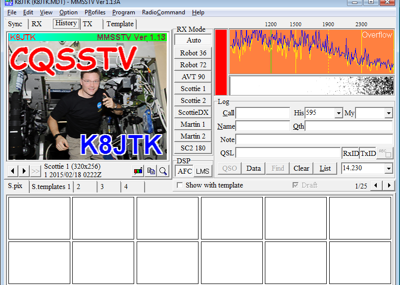
An exciting addition to some MFSK flavors is the ability to send small images. MFSK-16 can send images but not MFSK-8. A 320×256 sized color image took 4:26 using MFSK-16. It’s unlike Slow Scan TV where the software will size the image and overlay a template. The image needs to be fully prepared before it can be transmitted.

Transmit test: MFSK-16: 1:45, MFSK-8: 2:48.
Frequencies: 7072 kHz, 14072-14076 kHz.

Olivia

MFSK is good in poor band conditions but Olivia offers even better performance. Developed by Pawel – SP9VRC it is named after his daughter Olivia. It is called the JT65 of conversational modes because it’s incredibly slow but unlike JT65, it’s not a structured exchange.

There are different combinations of bandwidth and number of tones used, such as 500/16 is 500 Hz with 16 tones. Fldigi reverses these numbers for some odd reason and will read “Olivia 16 – 500.” Locking on to an Olivia signal may take 15 seconds. If the software is not decoding after that time, the bandwidth might be correct but the number of tones maybe wrong. For this reason, a call for “CQ” may take a minute or longer so stations can lock on and return a call. Be patient!

Olivia is great for poor band conditions because a trace may not be seen on the waterfall but a signal might be decoded! One example I share is a buddy of mine and I tried operating Olivia. We established contact and had strong traces on the waterfall using only 1.5 watts. We decided to compare it to sideband voice. We couldn’t contact each other on sideband until we were nearly up to 100 watts!

Transmit test: Olivia 500/16: 4:56, Olivia 500/8: 3:20.
Frequencies: 1835-1838 kHz, 3583.25 kHz, 3577 kHz, 7035-7038 kHz, 10141-10144 kHz, 14072-14075.65 kHz, 14106.5 kHz, 18102.65 kHz, 21072 kHz, 24922 kHz, 28122 kHz.

Software

I love and recommend software applications that are capable of operating multiple modes (multimode) using one application. This keeps the clutter down of installing multiple applications for each mode. The two I use are Digital Master 780 (DM780) as part of the Ham Radio Deluxe suite (http://ham-radio-deluxe.com/). This package is not free and only available on Windows. If that is out of your budget, then I recommend Fldigi (http://www.w1hkj.com/). It’s free, open source, and cross platform available on Windows, Mac, and Linux including Raspberry Pi. Both of these support many different modes and are constantly being updated and with newer modes.

MixW (http://mixw.net) and MultiPSK (http://f6cte.free.fr/index_anglais.htm) are alternatives and support most modes. There are specific mode applications like DigiPan (http://www.digipan.net/) for PSK and MMTTY (http://hamsoft.ca/pages/mmtty.php) for RTTY. Both are no longer maintained but are reported to work well with later versions of Windows. Other programs have known issues with versions of Windows later than Vista. Keep that in mind when trying older programs.

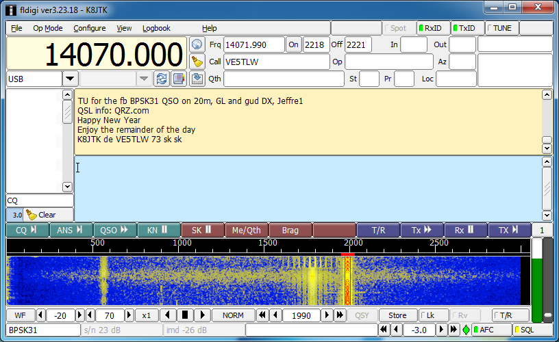
The software applications are similar in setup and operation. Exact labeling might be different from application to application. I am going to reference Fldigi, though not going in-depth with settings, it should get you started. Install Fldigi with the default options. A configuration wizard will appear the first time the application is started. Fill out all your station information. Select the sound card interface (USB Audio Codec for SignaLink). If the transceiver is using something other than the SignaLink for keying, select the appropriate radio and COM port for TX control.

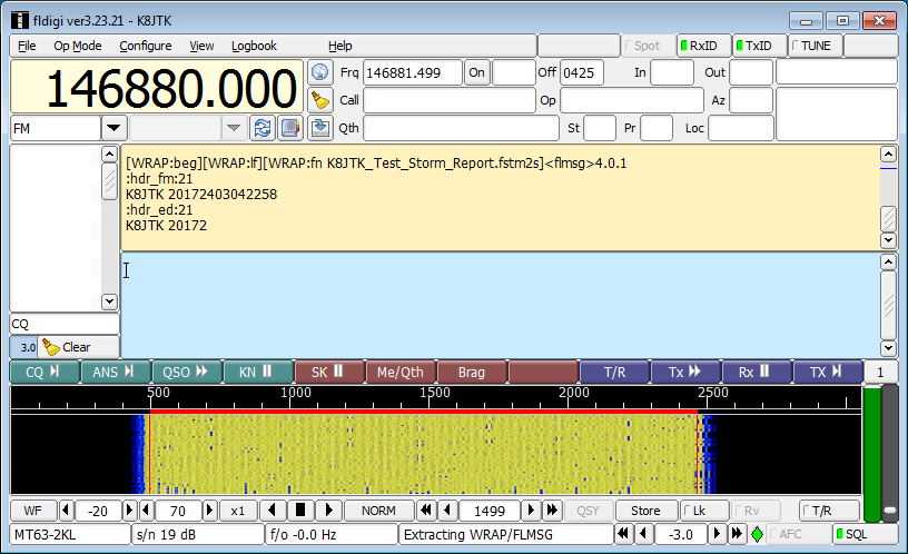
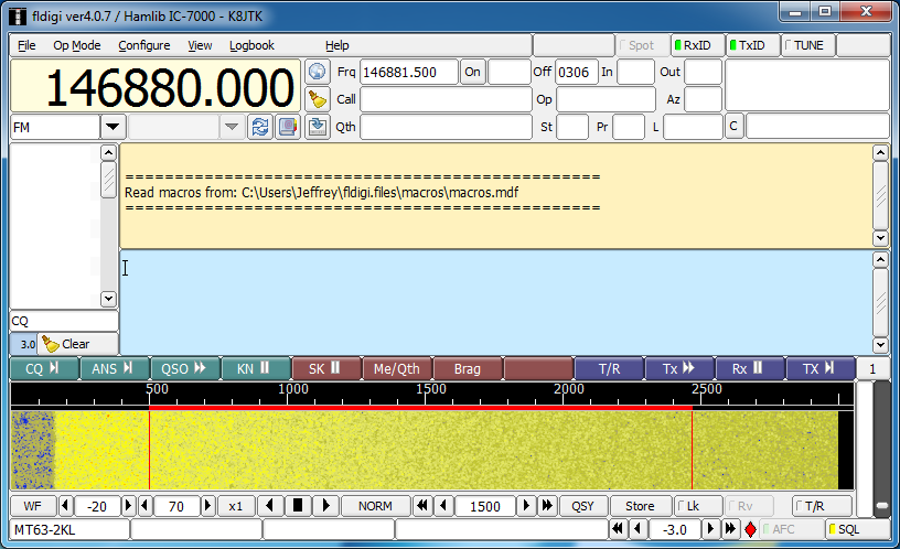
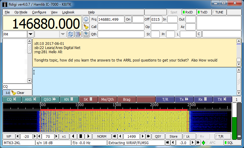
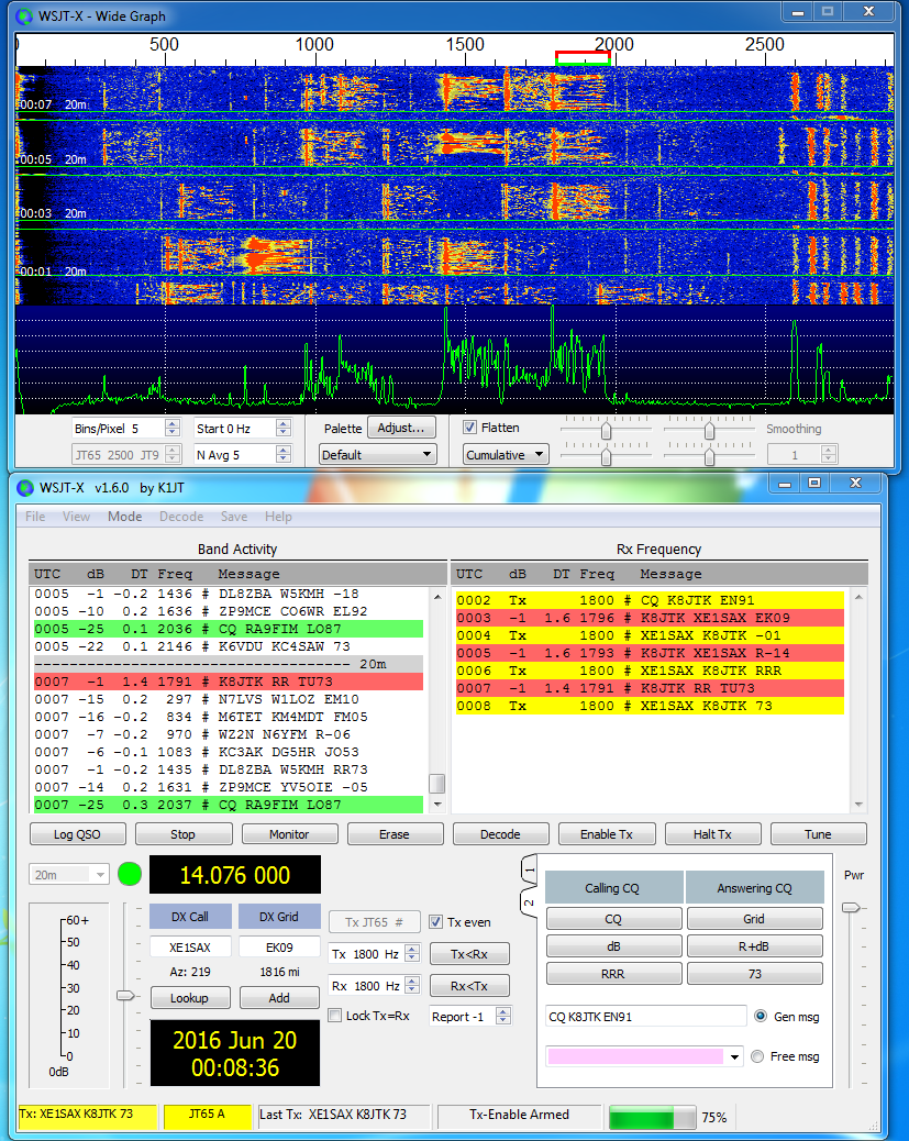
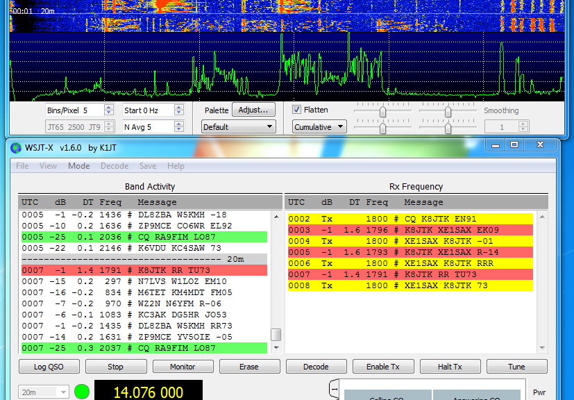
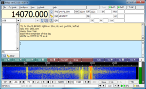
There are many parts to the Fldigi window. Standard menu options are seen like “File,” “Op Mode,” “Configure,” etc where operating modes or Fldigi configuration can be changed. Below that is Radio Control and Logging. When using internal logging, you’ll want the frequency to be correct. Rig control will help greately to automatically log the correct frequency as you change the VFO. Below that is the tan box where received messages will be displayed as well as transmitted messages will be copied here. The blue box is the transmit window where messages are composed for transmitting. If you have a white box to the left of the transmit and 
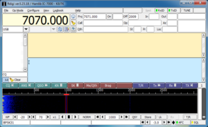
receive panes, this is the signal browser. This will display all conversations taking place, using the same mode, on the same frequency at once! Below the transmit text box is a line of colored buttons which are macros. Macros are pre-populated and commonly exchanged texts so you don’t have to keep typing them (right-click the button to edit). Below that is the frequency scale in Hz and waterfall. Below the waterfall are the waterfall controls. The line below that are the status messages and readings. To the right of the waterfall are two vertical white and a gray bars which indicate the strength of the decoded digital signal and squelch setting.

Tune your radio to one of the PSK frequencies to get setup. 20 meters is better during the day and 40 at night. The waterfall should start turning blue and yellow. If it is black, check the audio paths between the radio and computer, verify the audio input is set correctly in the Fldigi setup. Radios with a main and sub-band often cause confusion as to which band sends audio to the computer. If there is blue and yellow but a lot of black on the waterfall, check and disable radio filtering. Pro tip: the waterfall is a great educational place to visualize the filtering changes of the radio.

Now from the menu select “Op Mode,” “PSK”, then “BPSK-31.” To select a digital signal on the waterfall, simply click on the waterfall and the cursor will move to that location. Signals under the cursor will be displayed in the receive pane. It’s important to move the cursor on screen and do not adjust the radios VFO. Once a strong PSK signal is selected, you’ll notice the white squelch bar fills with green. The green needs to be above the light gray squelch slider to break squelch and decode. This is the first place to look if the cursor is over a signal but it is not decoding. Having the squelch set too high will miss decoding weaker signals and having the squelch too low will produce a lot of garbage text in the receive window. If a specific signal is strong but not decoding, the signal could also be multipathing, thus confusing the program. Watch conversations a good while to make sure you understand how the program works and for conversation syntax. Many programs have a “Signal Browser” or “Signal Sweeper” (DM780) which will decode multiple conversations at one time! In Fldigi, this can be broken out in a separate window under the “View” menu option.

Someone calling CQ will send CQ two-three times. I am K8JTK and Steve – W8HF will be the other station in these examples.

CQ CQ CQ de K8JTK K8JTK K8JTK

Repetition is good for weaker stations that might miss a letter or two. A responding station may respond with: K8JTK K8JTK de W8HF W8HF pse kn.

The two stations might begin the exchange using macros. These are good conversation starters. Macro messages typically include age of the operator, when they were licensed, radio and antenna, digital software program (Fldigi), computer operating system, physical location, etc, etc. This macro is called the “Brag” macro because you brag about your station. Beware though, for slower modes like Olivia, it can take a LONG time to send the same macro that takes seconds using PSK. The two stations could conclude the exchange or go back and forth typing out messages using the keyboard.

When receiving a message from another station, the responding station can begin typing a response in the blue transmit window even before the other station has finished transmitting. Always begin with something like “W8HF de K8JTK” so the other station knows you are responding to them, then continue with your message. If you’re conversing with a station and they don’t respond back after your message, they may have lost your signal, their program crashed, or became distracted. I typically wait 30 seconds – 1 minute and try a quick call back to the other station: W8HF W8HF W8HF de K8JTK K8JTK K8JTK, did I lose you? W8HF de K8JTK pse kn. I’ll try this 2-3 times and if they don’t return, I’ll log the QSO and move on.

End of transmissions should conclude with something like “btu Steve W8HF de K8JTK pse kn” noting the station is turning it back over to the other station. Concluding the conversation will end with something like: thx for QSO Steve, 73, W8HF de K8JTK sk. Other stations will end with a similar macro that includes their QSL information or when they upload their logs.

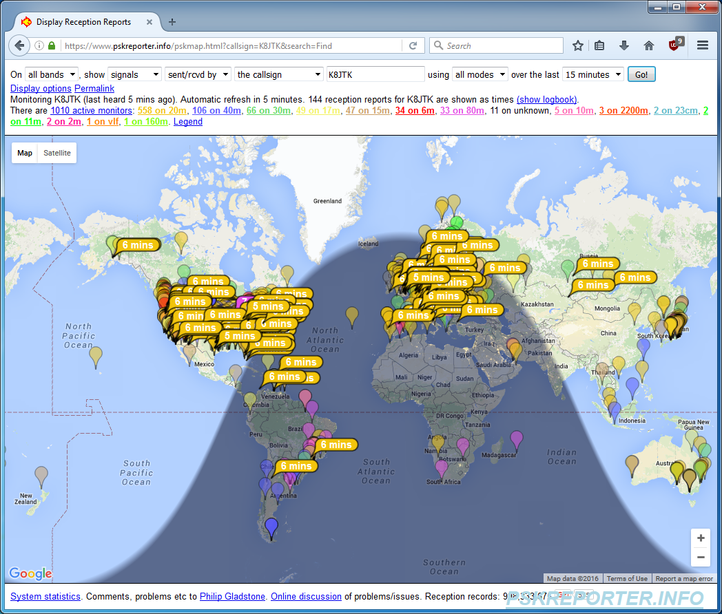
To transmit CQ, find an open space on the waterfall and click to bring the cursor to that spot. Tones will be generated in the same place as the cursor on the waterfall during transmission. Tune up on frequency and call CQ using the “CQ” macro. Some macros start and/or stop transmitting on their own. The “T/R” button under the waterfall is your best friend to start or stop transmitting. Some of the macros have the sequence “^r” at the end. This is an Fldigi command to change from transmit mode to receive mode aka transmission complete. This can be typed in manually at the end of messages too. PSK Reporter (http://pskreporter.info/) can be used just like JT65 to see how far you’re reaching.

Logging is fairly straight forward. RTTY and Olivia are logged as their respective mode only. BPSK is logged as PSK31, PSK63, etc. QPSK31, MFSK8, and MFSK16 are all logged as listed. If an RSQ was exchanged, log it accordingly. IMDs for either station can be recorded in the comments for future reference.

One idiosyncrasy with Fldigi: the position of the cursor in the transmit pane is critical. Fldigi will remain idle during transmission until the cursor is moved further down or moved to the end of the message. Many people are confused by this behavior and other programs don’t seem to follow this convention. For example if you had a sentence with “this that” and positioned the cursor after “this,” characters before the cursor will be transmitted until the point of the cursor was reached. The word “this” would be transmitted then Fldigi will remain idle in transmit mode until the cursor is moved. When moved, “that” will be transmitted until the program reaches the cursor again. Position the cursor at the end of the message during transmit and all will be well.

That’s it. These conversational modes are very open and very free form. Contesting will have a structure but casual operating is very informal. This outline can lead to operating other modes like Contestia, Thor, Throb, MT63, or Hell. Yes “Hell,” short for Hellschreiber, is a facsimile based mode where there is a reason everything is printed twice.

Find out more information:
“PSK31: A New Radio-Teletype Mode” by G3PLX: http://www.arrl.org/files/file/Technology/tis/info/pdf/x9907003.pdf
“Get on the Air with HF Digital” book: https://www.arrl.org/shop/Get-on-the-Air-with-HF-Digital
“RTTY/PSK31 for Radio Amateurs” book: https://www.arrl.org/shop/RTTY-PSK31-for-Radio-Amateurs-2nd-Edition/
“Nifty E-Z Guide to PSK31 Operation” book: https://www.arrl.org/shop/Nifty-E-Z-Guide-to-PSK31-Operation/
“How to get started with PSK-31 Ham Radio” by K7AGE on YouTube: https://www.youtube.com/playlist?list=PL8D7C6EBD6E2081E2

SSTV – Images via Radio presentations

Slow-Scan TV presentation.

Framework

The framework I chose to use for the presentation slides is called reveal.js. It is an HTML framework meaning it will run in any HTML 5 capable browser. Looks a little better than a PowerPoint presentation.

Navigation

Useful navigation keys in the presentation. In addition to navigating with the keys below, you can swipe (tables/smartphones) or use the navigation arrows on screen in the lower right.

Toggle full screen: press [F11].

Advance to the next slide: press [n] or [SPACEBAR].

Go back to the previous slide: press [p] or press and hold the [SHIFT] key while pressing the [SPACEBAR].

Display presentation overview: [ESC] then use the arrow keys or mouse to select a slide. [ESC] again will exit overview mode.

Links

Clickable links are colored in blue text.

Presentations

Three variations are available: presentation version is viewable in a browser. Printable version for printing or saving in a different format (Chrome, Chromium, and variants compatible only). Finally a PDF version.

They may take some time to load because I left original images untouched and some were a couple MB in file size.

Slides

The presentation is about 45 minutes in length.

Presentation version
Printable version
PDF version

This presentation was given at the following meetings:
Lake Erie Amateur Radio Association on 9/27/2016.
Geauga Amateur Radio Association on 9/25/2017.

Ohio Section Journal – The Technical Coordinator – August 2016 edition

One of the responsibilities of the Technical Coordinator in the Ohio Section is to submit something for the Section Journal. The Section Journal covers Amateur Radio related things happening in and around the ARRL Ohio Section. It is published by the Section Manager Scott – N8SY and articles are submitted by cabinet members.

Once my article is published in the Journal, I will also make it available on my site with a link to the published edition.

You can receive the Journal and other Ohio Section news by joining the mailing list Scott has setup. You do not need to be a member of the ARRL, Ohio Section, or even a ham to join the mailing list. Please sign up!

If you are an ARRL member and reside in the Ohio Section, update your mailing preferences to receive Ohio Section news in your inbox. Those residing outside the section will need to use the mailing list link above.
Updating your ARRL profile will deliver news from the section where you reside (if the leadership chooses to use this method).
Go to www.arrl.org and logon.
Click Edit your Profile.
You will be taken to the Edit Your Profile page. On the first tab Edit Info, verify your Email address is correct.
Click the Edit Email Subscriptions tab.
Check the News and information from your Division Director and Section Manager box.
Click Save.

Now without further ado…


Read the full edition at: http://n8sy2.blogspot.com/2016/08/august-edition-of-ohio-section-journal.html

THE TECHNICAL COORDINATOR
Jeff Kopcak – TC
k8jtk@arrl.net

DSCF5081 K8JTKHey Gang,

As I’m beginning this month’s article some nasty storms just ripped through Cleveland on the 11th. There were branches, trees, wires, power lines down, and road closures on the west side due to those hazards, including my QTH of Westlake. Luckily I’ve heard of no injuries. If you’re not part of the NWS Skywarn program, please consider joining as a spotter. Skywarn is a volunteer program that helps the local National Weather Service office know what’s happening on the ground and assists in warning people about dangerous weather conditions. Training typically happens in the early spring for spotters. Check with your local club or Skywarn organization.

The Republican Nation Convention went off without major incident in Cleveland. I was working from home and had the scanner on most of that week. Three major trunked radio systems were utilized: MARCS, the new MARCS-IP (Multi-Agency Radio Communications System), and GCRCN (Greater Cleveland Radio Communications Network). If you didn’t set a wildcard or use UniTrunker to watch those systems, you probably missed a lot of the event communications. There were about 12 primary talk groups on GCRCN where most of the action took place. These were previously unidentified so they were not in any lists or databases that use Radio Reference. A wildcard stops on any talk group whereas programming specific talk groups into the scanner will only stop on transmissions for those talk groups. The “old” MARCS system was shut down immediately following the convention as it was kept online largely for backup. It has been replaced by the MARCS-IP system.

This month we learned the sad news of Hara Arena’s closing. No more Hamvention at Hara Arena after 52 years. The Dayton Amateur Radio Association put into action their contingency plans. It was announced that Hamvention will still be in the Dayton area. The new location is The Greene County Fair and Expo Center located in Xenia, Ohio. Michael Kalter and Ron Cramer talked about the new location on Ham Nation for about 30 minutes in episode 259. Couple of links worth visiting:

-Why we are saddened by the loss of the Hara Arena: http://ad8bc.com/bc/?p=601
-Hamvention Announces Venue for 2017: http://hamvention.org/hamvention-announces-venue-for-2017/
-Ham Nation episode 259: https://twit.tv/shows/ham-nation/episodes/259, or YouTube link: https://www.youtube.com/watch?v=g_OaKmllEDY

One of our Technical Specialists, David KD8TWG, has been involved with setting up a DMR repeater in Cleveland. The frequency is 442.0875 (+5 MHz standard offset) using Color Code 1. The repeater is connected to the K4USD cBridge (http://www.k4usd.org/). On that website is a listing of the “standard DMR Logo configuration” for repeaters connected to the bridge. Right now, your code plug should follow the layout listed on the site. A cBridge is a feature that allows interconnecting of repeaters over the Internet and a Color Code is equivalent to a PL tone or DCS on analog repeaters.

When I picked up my DMR radio at Dayton, I found a code plug that had repeaters in Dayton and Columbus for the drive home. It was a nice opportunity to quickly get on the air with DMR but I kept threating myself to write my own. With the installation of the repeater in Cleveland, I took the opportunity to do just that. What is a “code plug?” Some history I found online notes the origins came from wire plugs, later jumpers, which were plugged into the radio to enable certain options or features. Since everything is now processor based, the term continues to stick with the radio world and is a fancy word for ‘radio configuration.’ It contains transmit/receive frequencies, tone selections, timeout values, IDs, configuration settings, etc. I used the one I found in Dayton as a reference. Tytera MD-380 There is also a sample one on K4USD’s site for my radio. I compared the two and designed mine the way I thought worked best. Just because someone designed a code plug one way doesn’t mean you can’t modify or do it differently. It’s analogous to one ham’s memory channels are not the same as another. In the end, it took about 3 hours to make mine! Keep in mind that was a lot of learning and comparing, in addition I programmed all 65 possible talk groups so I don’t have to add them in later. From discussions on the air indications are it took others a few hours as well. But my code plug works! I couldn’t be happier. Well OK I could, apparently I’m just far enough away that my 5 watts doesn’t quite make the trip. I took the radio to work and tested it from there.

I am writing an introductory series for the Wood County Amateur Radio Club on getting started in digital modes. The first few articles were for those who have never worked digital and want to upgrade their station. Remaining articles will focus on a specific mode. I’ve completed 3 so far (starting in February): an introduction, station setup, and working JT65/9. Published versions can be found at the club’s website WSJT-X Conversation in the CQ Chatter newsletter: http://wcarc.bgsu.edu/. As I point out in the second article, Technician class licensees can still participate. All of these sound card digital modes can be operated over FM simplex or even a net on a repeater using an HT! There are clear downsides like not being able to transmit as far as an HF station and occupying the full 10 to 15 kHz FM, even though the bandwidth of the audio generated by the computer is less. Yes, this defeats the purpose of narrow bandwidth modes. Someone wanting to learn and experiment with these modes may get bitten by the bug and lead to a license upgrade. That’s how I did it. I plan to write an article every 2-3 months.

My dad and I had the opportunity to join the Toledo Mobile Radio Association (TMRA) on August 10. They had Chris Wilson N0CSW, National Sales Manager for Yaesu talk about their System Fusion. Chris did make it clear that the company was paying for travel so there would be some ‘sales pitches.’ The presentation was short but the program ended up being driven by the audience with a lengthy question and answer session. Some things I learned: the DR-2X Yaesu DR-2Xrepeater announced at Dayton is not going to be a replacement for the DR-1X, though they may have improved on some shortcomings. The 2X is more of a full featured repeater. It will have the ability to operate dual receive and dual transmit (but not at the same time) creating two repeaters from one unit. They are including voice messaging (like club meeting announcements). Mailboxes were users can record messages for others. This reminds me of the mailboxes repeaters used to have when autopatches were more prevalent. The 2X can monitor a separate control channel for commands. This repeater will not support WiresX but will have “MSRL” (Multi-Site Repeater Linking) via an add-on Ethernet port. Their linking technology will allow the repeater to be linked over any IP based network, including mesh. This brought to mind an interesting use-case where multiple low profile/portable repeaters could be linked at sites with mesh such as air ports, hospitals, and Red Cross shelters. This would create a linked repeater system where not as many users would have to setup cross-banding or run to the other end of a hospital to reach a radio. In contrast, something similar can be done using the AllStar Linking system. At the meeting there was alot of: “I would like this feature/I don’t like this feature in the radio,” “we’re having this problem setting up the repeater to do X” kind of Q&A. My take away from that, their plan is to add features to radios by firmware update and not always release new radios.

In addition to all the work David KD8TWG has been doing to get DMR up and running in Cleveland, he’s been helping repair and upgrade analog repeaters, and setting up APRS IGates around town. He will be giving a presentation on APRS at the Lake Erie Amateur Radio Association’s club meeting on August 30th. Dinner starts at 6:30pm with the meeting at 7:30, don’t need to have dinner to attend the presentation. Haven’t seen an official announcement on location yet but it’s expected to be at the Play Arcade in Mayfield Hts (5900 Mayfield Rd, Mayfield Heights, OH). Check the LEARA website for updates and for dinner reservations: http://www.leara.org/.

Raspberry Pi 3I will be giving my introductory Raspberry Pi presentation at the Cuyahoga Amateur Radio Society meeting, September 13 at 7:30pm. It will be updated as there is new hardware and innovations available. Their meeting location is the Busch Funeral Home, 7501 Ridge Rd, Parma, Ohio. More: http://www.2cars.org/.

Thanks for reading and 73… de Jeff – K8JTK

Digital Communications in Amateur Radio: JT65 and JT9

This article appeared in the The Wood County Amateur Radio Club newsletter CQ Chatter August 2016 edition.

Read the rest of the series in the Digital Communications in Amateur Radio articles category.


My favorite digital mode has to be the “JTs” otherwise known as JT65 and JT9. Many have equated them to watching paint dry. Others call it the musical mode. I call it my ADD mode. Whatever you call ’em, JT65 has become one of the most popular digital modes second only to PSK. I call it my ADD mode because I can browse the web, watch TV, or write this article during the 7-minute exchange. But you better pay attention because it can still keep you on your toes!

JT65 and JT9 began with Nobel Prize Winner Dr. Joe Taylor – K1JT. One of Dr. Taylor’s passions was weak signal communications and moonbounce (EME). A signal is sent toward the moon at about 1.5 kW on VHF using large directional antenna arrays. The signal is reflected off the moon and received by an equally powerful station with large arrays. After the signal makes the 500,000 mile round trip, there wasn’t much left. CW was the only effective mode. In 2001, K1JT came up with JT65 which allowed hams to make Earth-Moon-Earth contacts with 150 W and 11-element beam antennas. Still not exactly easy but it made EME a possibility for many more hams. Years later it was discovered that JT65 works great on the HF bands too. It allows stations to make contacts without high power or gain antennas. This is perfect for hams that cannot have large or visible antennas. Over time, JT9 was added specifically for the LF, MF, and HF bands (“Work the World with JT65 and JT9”).

It’s not my intention to dive into the technicals of any mode but to give hams practical operating information. When talking about JT65 almost all information applies to JT9 as well. Both are highly time-synchronized. The computer’s clock must be as accurate as possible and within 2 seconds of other stations. One minute transmit and receive sequences are utilized. Transmitting happens within a one-minute window then the roles are reversed for the following minute. Stations begin transmitting 1 second after the beginning of the minute and stop 47.7 seconds later. In the remaining 11.3 seconds applications decode received signals, display them on screen, and receiving stations get their message ready to transmit. The total exchange takes about 7 minutes. More if the message is lost or not decoded. Being such a robust protocol doesn’t leave room for long messages meaning it’s not a conversational mode. The maximum message length is 13 characters with the intent of limiting the exchange to call signs and signal reports. Below is an actual exchange. The first column is the time, second is the exchange, third is the exchange translation. Exchange beings at 01:00 UTC and completes at 01:07. In messages with two call signs, the receiving station is to the left and the transmitting station to the right.

0100 CQ K8JTK EN91
I’m calling CQ from grid square EN91.

0101 K8JTK K5ND EM12
K5ND is returning my CQ from grid square EM12.

0102 K5ND K8JTK -01
I reply to K5ND with his signal report of -1 db (RST Sent).

0103 K8JTK K5ND R-05
K5ND responds with my signal report of -5 db (RST “R”eceived).

0104 K5ND K8JTK RRR
I respond with “roger-roger-roger.”

0105 K8JTK K5ND 73
K5ND responds with best wishes.

0106 K5ND K8JTK 73
I respond with best wishes.

Differences between JT65 & JT9 are bandwidth and signal reports. JT65 takes up just under 180 Hz and about 16 Hz for JT9. JT9 is much better for spectrum efficiency and uses less power due to narrower bandwidth. The JT65 sub-band can often be seen with multiple overlapping signals and they usually decode correctly. JT9 can have ten-times the signals but decoding of overlapping signals is much less likely to happen. Signal reports range from -1 to -30 db signal-to-noise in JT65. The lowest I’ve seen is -27. They are capped at a -1 db upper limit to keep somewhat consistent with EME reports. JT9 is extended to give more accurate signal reports with a range from -50 to +49 db. The limits I’ve seen are -27 and +15. Propagation is comparable between the two modes. JT65 is the overwhelming favorite of operators.

JT65 & JT9 have their own sub-bands. Below is a listing of those frequencies. JT9 is typically 2 kHz above the JT65 frequency. USB is the mode regardless of band.

JT65 JT9
1838 1838
3576 3578
7076 7078
10138 10140
14076 14078
18102 18104
21076 21078
24917 24919
28076 28078
50276 50278

Software is available on all major platforms. Ham Radio Deluxe is expected to include JT65 in the very near future.

Windows:
JT65-HF (http://jt65-hf.sourceforge.net/). It’s very reliable and I’ve only noticed one issue where free hand text doesn’t always transmit. This is the old standard but no longer in development.

JT65-HF-HB9HQX-Edition (http://jt65hfhb9hqxedi.sourceforge.net/). This is the replacement for the above. It’s built on the same code-base so look and feel are similar. The developer has implemented many new useful features. I recommend using this one for newcomers.

Windows/Mac/Linux:
WSJT-X (http://physics.princeton.edu/pulsar/k1jt/wsjtx.html). Software released by K1JT. This seems to give the most accurate signal reports. It’s the only program that currently implements JT9. WSJT-X is the program that I use.

WSJT-X Conversation
WSJT-X application showing QSO with XE1SAX

Application setup is fairly straight forward. In the setup, enter your call sign and grid square. If you don’t know your grid square, check QRZ or enter your address on: http://www.levinecentral.com/ham/grid_square.php. Choose the correct sound input/output devices. Configure Rig Control/PTT if needed. Rig Control is not required but helpful when using the internal logging methods.

Before starting any of the applications, ALWAYS sync your computer’s clock with the Internet. In Windows, go to the Control Panel, Date and Time, Internet Time tab, Change settings, click Update now. Most Linux distributions need to invoke ‘ntpdate.’ One feature of the HB9HQX version is automatic time syncing every 15 minutes.

All programs have the same general layout and operate in the same manner. They have a waterfall showing signals received and display markers indicating active transmit and receive windows. These can be moved by clicking on the waterfall.

Conversational buttons and boxes are often labeled Calling CQ and Answering CQ. These buttons automatically generate text during the conversation (following the standard exchange format). Free Text/Message is for free hand text. Other buttons will enable and disable transmitting. Halt will interrupt the transmission midway through. Even/odd indicates which minute you will transmit (only applies to calling CQ). It has no effect when answering a CQ because the software will transmit in the next minute.

The Signal Decoding window is the most important because this is where all conversation exchanges are displayed. A couple labels are seen: UTC – time the signal was decoded, Sync – measurement of the sync signal — higher the better, DT – time difference between decoded station and yours — should be less than 2 seconds, DF – frequency deviation above or below the center point in Hz, and finally the Exchange or Message text. Colors are frequently used to distinguish items of importance. Green is a station calling CQ, red is a message/exchange intended for your station (contains your call sign), gray is exchanges between other stations.

Luckily the software takes care of much of the exchange. It generates response messages by double-clicking a received line. Stations that don’t follow the standard format can easily confuse the software. This is where it will keep you on your toes. If you’re not careful you can end up sending a message twice or not properly advancing to the next message in the exchange. The software does not automatically advance the conversation for you. If things go off the rails, use the appropriate conversational button to get things back on track.

The Free Text field can be used for noting your power, antenna, or sending holiday greetings. These messages are often in place of the 73’s and will not show up in red because no call signs are included. You may see “30W DPL” (I’m running 30 watts into a di-pole antenna), “50W LOOP” (I’m running 50 watts into a loop antenna), “THX 4 NM” (we’ve worked before, thanks for the contact using a new mode from previous contacts), “THX 4NB” (we’ve worked before, thanks for the contact on a new band), “SRY/SRI NO DECODE” (I see a signal on the waterfall but it did not decode) you’ll see this one but it’s not commonly used, “MERRY XMAS” –you get the idea. It’s only 13 characters. Be careful not to baffle the user and you have to be quick. There are some I’ve received that I still have no idea what they mean.

In the JT’s it’s ether a clean decode or nothing at all. No in between. When I see a signal on the waterfall and the message doesn’t decode, I always send my last message again. Some stations will not transmit in the following minute. Other stations (wrongly) move on in the conversation. Then I have to use free hand text to send “SIG RPT?” or similar because I didn’t receive my signal report. At minimum, I make sure RSTs (reliability – strength – tone) have been exchanged and won’t log the contact until “RRR” has been sent/received. Some QSLs I received go as far to log the DF frequency. I’ve only logged the center frequency.

After you feel comfortable monitoring activity, double-click a green “CQ.” The Generated Text field will update with your call sign, their call sign, and your grid square. You’re off! Also, refer back to article two for station/DSP/audio setup. I’ve seen some of the worst over modulated signals on JT65. JT users are really good about uploading spots to PSK Reporter (https://www.pskreporter.info/pskmap.html). You can use it as a ‘reverse beacon’ network to see where your signal is propagating.

PSK Reporter Spots
PSK Reporter application showing received stations worldwide

It’s a lot to take in but an extremely fun mode to work. Find out more information:

Amateur Logic.TV on JT65: https://youtu.be/L7e5NbqhbVU?t=28m10s

QST article: http://www.arrl.org/files/file/Get%20on%20the%20Air%20with%20HF%20Digital/FORD%20JT.pdf

PowerPoint introduction: http://www.arrl.org/files/file/Get%20on%20the%20Air%20with%20HF%20Digital/Getting%20Started%20with%20JT65%20on%20the%20HF%20Bands.pps

“Work the World with JT65 and JT9” book: http://www.arrl.org/shop/Work-the-World-with-JT65-and-JT9/

Ohio Section Journal – The Technical Coordinator – July 2016 edition

One of the responsibilities of the Technical Coordinator in the Ohio Section is to submit something for the Section Journal. The Section Journal covers Amateur Radio related things happening in and around the ARRL Ohio Section. It is published by the Section Manager Scott – N8SY and articles are submitted by cabinet members.

Once my article is published in the Journal, I will also make it available on my site with a link to the published edition.

You can receive the Journal and other Ohio Section news by joining the mailing list Scott has setup. You do not need to be a member of the ARRL, Ohio Section, or even a ham to join the mailing list. Please sign up!

If you are an ARRL member and reside in the Ohio Section, update your mailing preferences to receive Ohio Section news in your inbox. Those residing outside the section will need to use the mailing list link above.
Updating your ARRL profile will deliver news from the section where you reside (if the leadership chooses to use this method).
Go to www.arrl.org and logon.
Click Edit your Profile.
You will be taken to the Edit Your Profile page. On the first tab Edit Info, verify your Email address is correct.
Click the Edit Email Subscriptions tab.
Check the News and information from your Division Director and Section Manager box.
Click Save.

Now without further ado…


Read the full edition at: http://n8sy2.blogspot.com/2016/07/july-issue-of-ohio-section-journal.html

THE TECHNICAL COORDINATOR
Jeff Kopcak – TC
k8jtk@arrl.net

DSCF5081 K8JTKHey Gang,
It’s been a busy month with ham radio holidays and national holidays. June was a great operating month for me as I had taken some time off work after Dayton. Since I really hadn’t been on the air the first half of the year, I spent a lot of time catching up. Heck April I made a total of three contacts. Bleh. I racked up 130 contacts including Field Day and 17 National Park activations. As usual I’m coming to the party late on NPOTA so I’m getting there. Our own Affiliated Clubs Coordinator John KD8MQ has given many updates in past editions of the Journal; check them out. More: https://npota.arrl.org/

I will tell you no matter what you do for Field Day, you’re always going to have a good time. If you get together with a club or some buddies, there are going to be good stories too. This year I took a different approach and decided to operate as a 1D station. Still had a good time. It gave me a chance to refresh my memory and practice using the Digital Signal Processing (DSP) and filtering features of my radio. As one would expect, there were stations all over the place. The bands weren’t that great either. I would hear a station but not clearly. I used different Automatic Gain Control (AGC) settings, Noise Reduction, filters, Passband Tuning (PBT), the whole nine yards. If I wasn’t hearing much scanning around, I would go work on something else and come back later to work more stations. In total made 30 contacts mostly on 40m from the home QTH.

The following weekend was Canada Day and the Independence Day holiday weekend. First up was the Radio Amateurs of Canada (RAC) Canada Day contest on July 1st. Since I’m a station outside Canada, the exchange was RST and serial number. The serial number was the number of Canadian stations worked during the contest. I worked 14 stations total over the 24 hour contest.

Then (of course) starting Friday morning was the 13 Colonies Special Event. There is one station in each of the 13 original colonies and two bonus stations. Bonus stations are Philadelphia where independence was declared and England for the “British Standard” contact. Things were going well for me. I started out working 9 stations on Friday night and 5 on Saturday morning. Then nothing. The British bonus station was eluding me. I kept trying when they were calling on sideband but they never came back to me or by the time they went through the numbers and got to 8 – they were down in the noise. It wasn’t looking good. In literally the 11th hour, I finally made contact with England on PSK for my clean sweep! I’ll be sending away for my certificate and sending out QSL cards soon. If you worked any of the 13 colony stations, please support them by making a donation or sending in for a certificate. Many stations took time out of their holiday weekend to put on another successful event. More: http://www.13colonies.info/

Last month I mentioned the Portage County Amateur Radio Service was going to have an Earth-moon-earth presentation for their July meeting. I’ve never experienced or knew anyone that worked EME so this was a presentation I did not want to miss. It was a bit of a drive in rush-hour traffic from downtown Cleveland. Nonetheless, food was great and it was an excellent presentation. Tony WA8RJF talked about the properties and theories involved making EME contacts, early days of EME needing monster arrays with gain antennas and rotor controls the size of two truck-beds –in one case. Then he talked about JT65 being the game changer to make EME communication more accessible to regular hams. The majority of my HF contacts are JT65 so a lot of it hit home for me. JT65 was originally created for EME but later adapted to HF and has become the second most popular digital mode. Thanks to Tony and PCARS for allowing me to be a guest at their meeting.

ATV ID3Speaking of modes I haven’t yet operated, the QSO Today podcast interviewed Art Towslee WA8RMC of Westerville who is heavily involved with ATV (Amateur Television, sometimes called Fast Scan TV). ATV uses video and audio much like a commercial broadcast station. In many ways you are operating from your own studio with a video camera, microphone, lights, or other video sources. In the podcast they about Art’s history, knowledge, and involvement in projects to move ATV forward using Digital TV standards. With the introduction of Digital TV, quadcopters and 4K resolution, ATV is becoming popular once again. Slow Scan TV in contrast is sending a single still image over the air. More: http://www.qsotoday.com/podcasts/wa8rmc and https://atco.tv/

DCC2016web

The TAPR Digital Communications Conference is coming up September 16-18 in St. Petersburg, FL. The list of speakers and forums haven’t yet been released but topics will likely include Software Defined Radios, digital voice modes (D-STAR, Fusion, DMR, P25, Codec2, FreeDV), digital satellite communications, APRS, and the like. More: https://www.tapr.org/dcc.html

wrt54gl-640x411In a great article from ARS Technica, they talk about the Linksys WRT54GL router that is 11 years old and still making millions for Linksys. This router came out in 2005 but really had an ecosystem built around it. The router was Open Sourced making it easily modifiable and turning it into a much more powerful router. We hams have seen this first hand as these are one of the more popular models used in Mesh Networking. Linksys said they’ll continue to make the router while suppliers keep selling the parts; great news for Mesh users. More: http://arstechnica.com/information-technology/2016/07/the-wrt54gl-a-54mbps-router-from-2005-still-makes-millions-for-linksys/

On a sad note that hits close home, especially those in Cleveland. At AES logothe end of July, Amateur Radio equipment retailer Amateur Electronic Supply (AES) will be closing for good. We all have stories about the long time retailer. I liked browsing the show room and playing with the radios on display. They were always helpful to their customers. It’s sad to see a retailer leave and friends lose their job. 73’s to the AES crew. You will be missed. More: http://www.arrl.org/news/amateur-electronic-supply-closing-after-59-years-in-business

That’s about it for this month. With the conventions going on in the state, everyone please stay safe. As I’m writing this a few days before the RNC, there are plenty of changes happening in Downtown Cleveland: unmarked SUVs, helicopters flying around, “Cell on Wheels” (COW, portable cell sites) popping up, temporary stages going up, and TV equipment trucks. My company has made previsions for us to work remotely. Those with a P25 digital trunked capable scanner in the Cleveland area will probably find most activity on the Ohio MARCS-IP (Multi-Agency Radio Communications) and GCRCN (Greater Cleveland Radio Communications Network) systems. The old MARCS 3.5 legacy system is going to be kept on-line as a backup to the MARCS-IP system. After the convention that system is expected to be fully shutdown. No definitive word on talk-groups to listen to but keep an eye to the Radio Reference Ohio forum and frequency database pages as things gear up.

Thanks for reading and 73… de Jeff – K8JTK